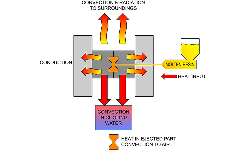
This page is designed to show the calculation steps to figure heat transfer from an injection mold through the clamp plate and into the platen.
Heat Transfer Rate – Q = ΔT/R
Variables
ΔT = Temperature difference between the hot and cold sides of a plate
R = Resistance = L/(K x A)
A = surface area of the plate
K = heat transfer coefficient (BTU/hr/Ft2/in./ ΔT)
L = plate thickness, ft.
Assume a 12” square P-20 steel clamp plate with K = 16.8, Area = 1 sq.ft., thickness = 1.875”. Call this value R1 as follows:
L = 1.875/12 = .149 ft.
A = 1 sq.ft.
Resistance R1 = .149 ft./(16.8 x 1 sq.ft.) = .0089
If the A-plate of the mold is kept at 175°F by a mold temperature control and the clamp plate is clamped to the machine platen which might be around 90°F we can estimate that ΔT (between the hot and cool sides of the clamp plate) = 85°F
Heat Transfer Rate, Q = ΔT/R1 = 85/.0089 = 9551 BTU/hr.
Next, for an insulator board 1/2” thick we can calculate an R2 value as follows: L = .50”/12/in/ft = .042 ft. The heat transfer coefficient of the insulator board is 1.9, so the math goes like this:
Resistance R2 = .042/(1.9 x 1) = .022
With the ½” insulator board added the calculation is as follows:
Heat Transfer Rate, Q = ΔT/(R1 + R2) = 85/(.0089 + .022) = 85/.031 = 2742 BTU/hr.
SUMMARY
Without the insulator board, mold at 175°F, heat transfer through the clamp plate and into the platen is approximately:
Q = ΔT/R1 = 85/.0089 = 9551 BTU/hr
With a ½” insulator board with a heat transfer coefficient of 1.9 the heat transfer rate to the platen is approximately:
Q = ΔT/(R1 + R2) = 85/(.0089+.022) = 85/.031 = 2742 BTU/hr.
Savings is 6809 BTU/hr.
This change results in lower energy cost and greater process stability.


