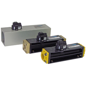
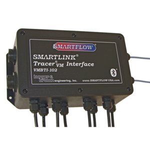
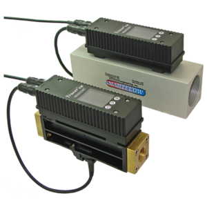
Tracer®VM Electronic Flow Meters
About Smartflow Flow Meters
Choose a flow meter based on the application, operating temperature, and pressures.
Indication options range from visual confirmation to digital data acquisition and storage.
Sizes start at 1/4″NPT and BSPP with common sizes up to 3″ NPT.
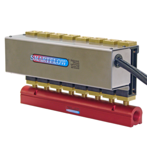
Modular design allows customized assembly with gauges and regulators onto manifolds for personalized flow rate monitoring and control.
Common Questions About Flow Meters
No. For best results, the flow meters and regulators or valves should be placed on the return side of the loop, or after the water has exited the mold.
All surfaces inside the cooling circuits should be in direct contact with the cooling water. If you create a restriction going into the cooling circuits, you may create a trickle of water flow that does not make full contact with cooling channels and could adversely affect molded part quality.
The flow rate of the cooling water will be the same on the supply side as it is on the return side unless you have a leak.
Stated accuracy is the percentage variation of the top of the range. +/-5% accuracy on a meter with 8 gallons per minute at the upper end will display no more than +0.4 gallons or -0.4 gallons from actual.
Most moving parts can be easily replaced on our mechanical flow meters in the field. We recommend factory replacement of electronic flow sensors whenever possible.
Yes. Tracer®VM Flow Meters use a solid-state sensor, otherwise known as “vortex shedding”. These sensors are not serviceable. However, they are easily replaced without disassembling or removing a meter from service.


