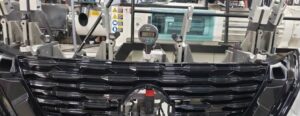
Problem: An automotive part manufacturer had trouble maintaining dimensional stability when molding a large plastic grille. The center of the finished part had an unacceptable deformation of more than 1mm. The part was ejected before the plastic was sufficiently hardened. Cycle times were adversely affected. Part quality was not acceptable.
Target ΔT at the parting line was 10-20°F. The actual measured ΔT at the parting line was between 20-30°F.
Beginning conditions: The injection mold cooling consisted of 16 zones, 3/8” lines, with 90°F cooling water. The manufacturer was using three temperature control units to maintain the water temperature. With all cooling lines wide open, some zones showed a flow rate of 2.5 gallons per minute. Flow meters on 5 zones showed no measurable flow.
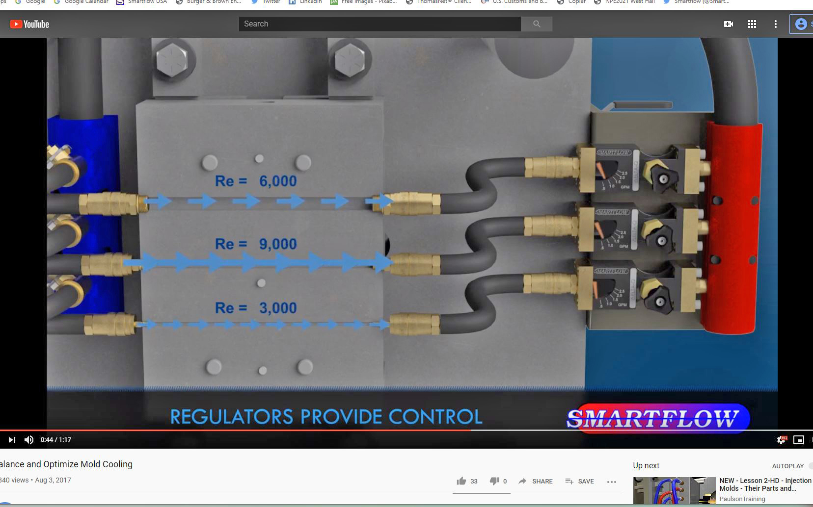
Process: Using the Turbulent Flow Rate Calculator, we determined the flow rate required to achieve the target Reynolds Number of 6000. The resulting flow rate with the given cooling parameters was 0.85 gallons per minute.
Solution: By reducing the flow rate in each zone to 1 gallon per minute, extra flow capacity was made available to the zones that previously showed no measurable flow. Cooling water will follow the path of least resistance. By controlling the flow available to the zones with less resistance, cooling water was forced into the more constricted flow paths. This allowed the cooling water to flow into all zones in a balanced and optimized manner.

Result: Dimensional stability was achieved in the finished part. The manufacturer reduced the number of temperature control units from 3 to 2, saving energy and TCU equipment usage. Cycle times were normalized, and production targets were achieved.
Smartflow Products Used: Brass Flow Regulators with IceCube™ Flow Meters including Temperature Gauges and Quick Disconnect Fittings: FR3-E-80 and Turbulent Flow Calculator