Contact Us
Speed up your tool changes by using SMED Friendly Accessories from Smartflow.

Includes Programmable SPDT Switch, Analog Output, and FCI (Flow Characteristic Indicator) Technology with New Totalizer Function
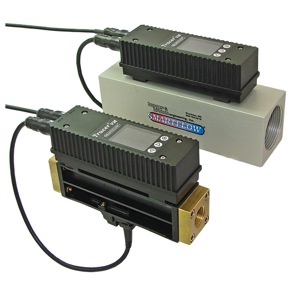
TracerVM Electronic Flowmeter with User Interface employs reliable vortex shedding technology to monitor liquid flow rate and temperature. The newly designed control circuit provides programmable switch set points for high or low flow or temperature and turbulent flow rate (FCI Technology). Analog Outputs for flow and temperature are selectable: 0.5 to 3.5/4.1V, 0 to 5V. or 0 to 10V, for connection to data acquisition system or PLC. A totalizing function is unique to this user interface with volume display from a selected point. Reynolds Number display and BTU’s per minute calculation are unique in the industry and come standard with this model.
Every unit is equipped with an internal rechargeable battery for temporary operation without attachment to a direct power source. Standard cable is supplied with loose wire leads for customer termination. Optional AC wall adapter cable provides DC power for charging purposes. Optional cable is available for connection to RJG eDart System™.
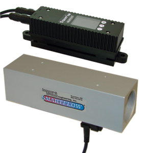
This flowmeter may be ordered with remotely mounted electronics. The LCD Display and controls can be positioned up to 9.5 feet away from the flow body.
Sealed pushbuttons configure the flowmeter and switch operations through brightly colored LCD and user-friendly menus. The SPDT switch can be wired directly to an alarm circuit in a process controller or other peripheral equipment such as low-voltage stack lights.
NIST Traceable Calibration is available.

| Connection Size | Flow Range LPM | Flow Range GPM |
|---|---|---|
| 3/8″ & 1/2″ | 1 to 18 | .3 to 4.8 |
| 3/8″ & 1/2″ | 2 to 40 | .5 to 10.6 |
| 3/4″ & 1″ | 5 to 100 | 1.3 to 26.4 |
| 1″ & 1-1/2″ | 10 to 200 | 2.6 to 52.8 |
Wetted Parts:
Environmental:
TracerVM Flow Meter with User Interface Catalog
TracerVM Flow Meter with User Interface Catalog (Español)
TracerVM Flow Meter with User Interface Instructions
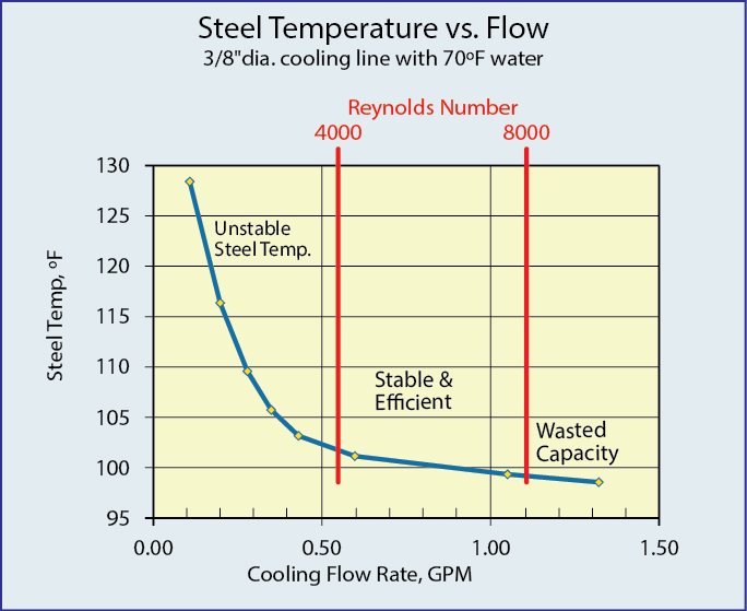
is the point at which cooling efficiency is optimized. Flow rates higher than the point of turbulent flow provide diminishing improvements in the cooling rate. Using FCI Technology, systemic cooling water flow can be optimized, conserving water and maximizing cooling plantwide without plumbing changes. “TF” displays when Turbulent Flow is present within the Tracer flowmeter.
